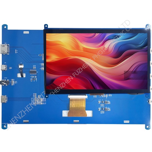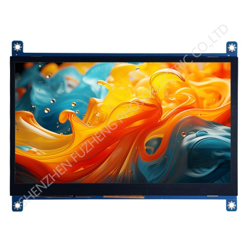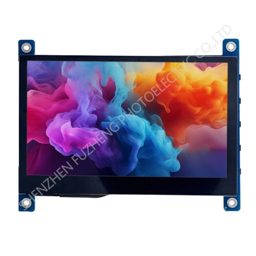
7 inch HDMI display module 1024x600

Item | Standard Value | Unit |
Display Size | 7 inch | -- |
Resolution | 1024x600 | -- |
Display mode | Normally Black | |
Viewing direction | ALL | |
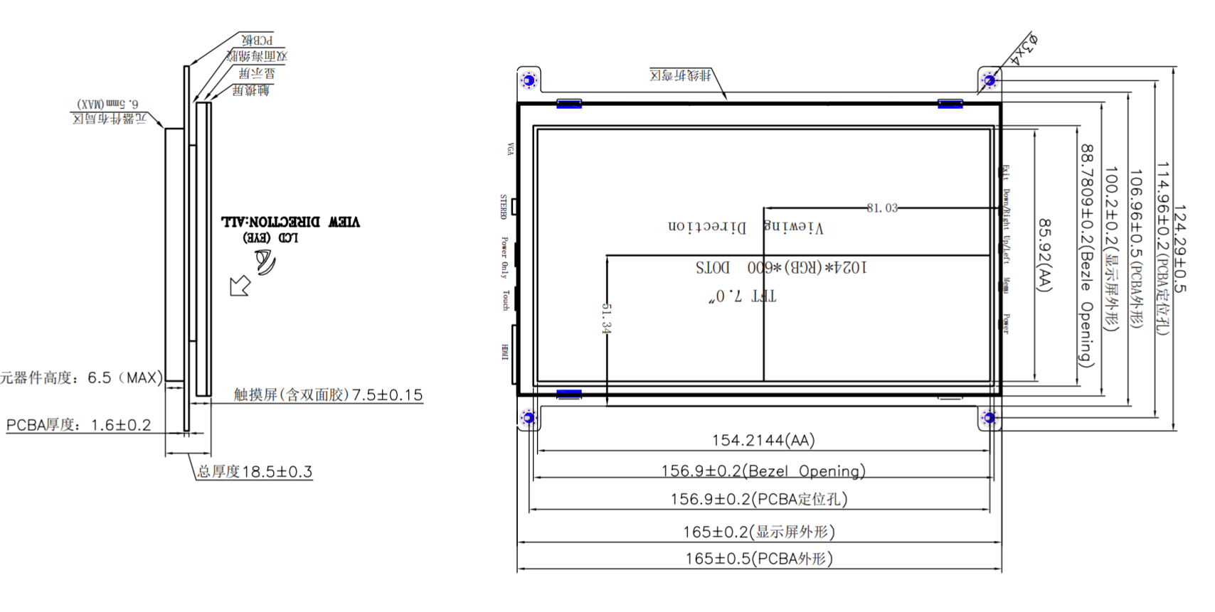
Module outline (HxVxD) | 165(H) ×124.3(V) ×18.5(T) | mm |
Active Area | 154.2144(H) *85.92(V) | mm |
Pixel pitch | 50.2(H) ×143.2(V) | um |
Interface | HDMI | - |
Touch interface | Michael USB | - |
Power interface | Michael USB | - |
Backlight Type | 3*7 chips white LEDS, | - |
Electrical Specifications
Parameter | Symbol | Values | Unit | Remark | ||
Min. | Typ. | Max. | ||||
Touch supply voltage | VDD | 4.5 | 5 | 5.5 | V | |
Power supply voltage | VDD | 4.5 | 5 | 5.5 | V | |
Notes :
The power only one power supply method is needed;
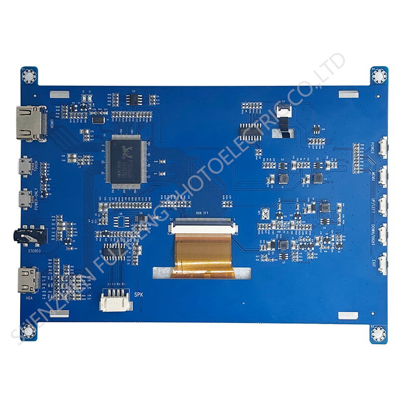
Interface Connections
Pin.No | Symbol | Function |
1 | HDMI | HDMI Input |
2 | TOUCH | Touch function and power supply Input |
3 | POWER | Only power supply Input |
4 | STEREO | Aidio ouput |
5 | MINI-HDMI | VGA input |
6 | SPK | Speaker ouput |
7 | RGB-TFT | 50PIN RGB-TFT ouput |
8 | TP | 6PIN TOUCH Input |
9 | POWER-KEY | Switch KEY |
10 | MEMU-KEY | OSD KEY |
11 | UPDN-KEY | Volume+/Updn-KEY |
12 | DOWN-KEY | Volume-/Down-KEY |
13 | EXIT | EXIT OSD/Input source switching-KEY |
5.0 Electro-Optical Characteristics
Parameter | Symbol | Condition | Min. | Typ. | Max. | Unit | Remark | |
Viewing Angle range | Horizontal | Θ3 |
CR > 10 | - | 80 | - | Deg. |
Note 1 |
Θ9 | - | 80 | - | Deg. | ||||
Vertical | Θ12 | - | 80 | - | Deg. | |||
Θ6 | - | 80 | - | Deg. | ||||
Luminance | CR |
Θ = 0° | - | 500 | - | Note 2 | ||
White Chromaticity | Xw | 0.276 | 0.306 | 0.336 |
Note 4 | |||
Yw | 0.314 | 0.344 | 0.374 | |||||
Reproduction of color (C light) | Red | Rx | 0.567 | 0.597 | 0.627 | |||
Ry | 0.289 | 0.319 | 0.349 | |||||
Green | Gx | 0.282 | 0.312 | 0.342 | ||||
Gy | 0.537 | 0.567 | 0.597 | |||||
Blue | Bx | 0.118 | 0.148 | 0.179 | ||||
By | 0.128 | 0.158 | 0.188 | |||||
Color Gamut (C light) | 50 | % | ||||||
Note :
1. Viewing angle is the angle at which the contrast ratio is greater than 10. The viewing angles are determined for the horizontal or 3, 9 o’clock direction and the vertical or 6, 12 o’clock direction with respect to the optical axis which is normal to the LCD surface (see FIGURE 1)
2. Contrast measurements shall be made at viewing angle of Θ= 0 and at the center of the LCD surface. Luminance shall be measured with all pixels in the view field set first to white, then to the dark (black) state . (see FIGURE1) Luminance Contrast Ratio (CR) is defined mathematically.
Brightness of Non-selected Segment (B2)
![]() Brightness of Selected Segment (B1)
Brightness of Selected Segment (B1)
2. Transmittance is the Value with WV Polarizer and BLU
4. The color chromaticity coordinates specified in Table 5 shall be calculated from the spectral data measured with all pixels first in red, green, blue and white. Measurements shall be made at the center of the panel.
5. The electro-optical response time measurements shall be made as FIGURE 3 by switching the “data” input signal ON and OFF. The times needed for the luminance to change from 10% to 90% is Tr, and 90% to 10% is Td.
6.0 Relia Bility Test Items
NO. | Test Item | Test condition | Criterion |
1 | High Temperature Storage | 70℃±2℃ 24H Restore 2H at 25℃ Power off | |
2 | Low Temperature Storage | 0℃±2℃ 24H Restore 2H at 25℃ Power off | |
3 | High Temperature Operation | 70℃±2℃ 24H Restore 2H at 25℃ Power on | |
4 | Low Temperature Operation | 0℃±2℃ 24H Restore 2H at 25℃ Power on | |
5 | High Temperature & Humidity Operation | 60℃±2℃ 90%RH 96H Power on | |
6 | Temperature Cycle | 0℃←→25℃←→70℃ 30min 5min 30min after 10 cycle, Restore 2H at 25℃ Power off | Aftertesting,cosmetic and electrical defects should not happen.
|
7 | Vibration Test | 10Hz~150Hz, 100m/s2, 120min | |
8 | Shock Test | Half-sinewave,300m/s2,11ms |