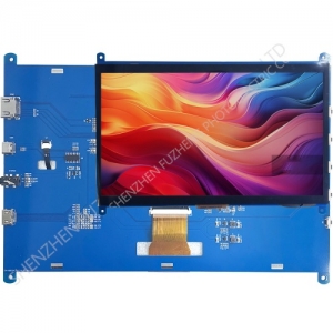
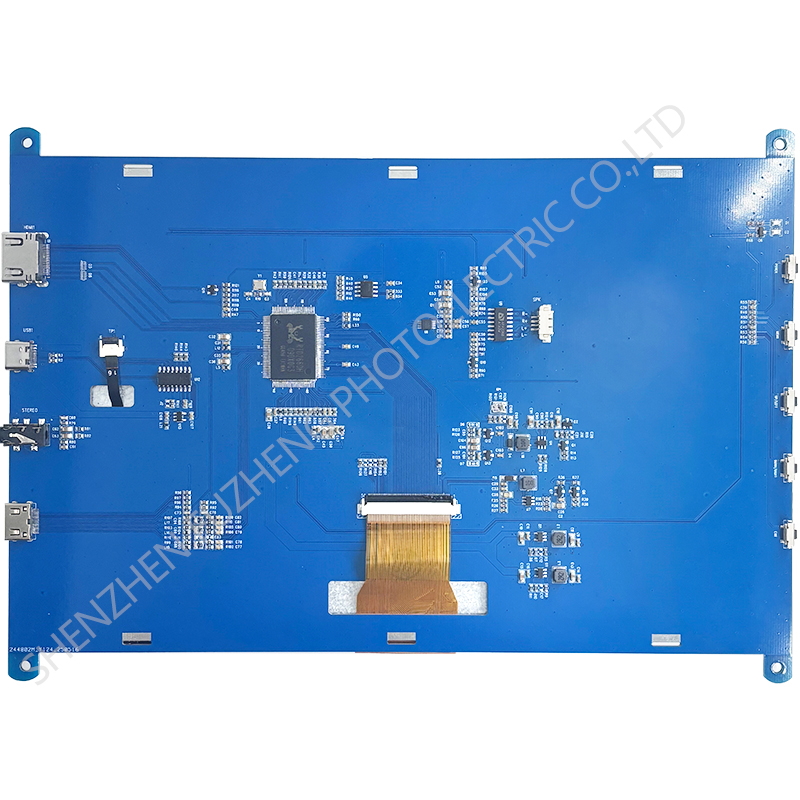
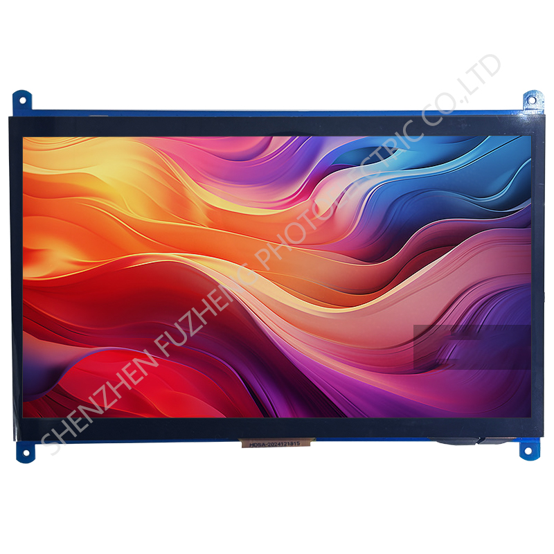
10 inch HDMI TFT display module 1024x600
The FZ10HDMI+LCD+CTP adapter board is a driver board designed specifically for digital LCD modules. It uses highly integrated single-chip IC's and fewer peripheral electronic components, providing stable performance and excellent display effects.
Item | Standard Value | Unit |
Display Size | 10.1 inch | -- |
Resolution | 1024x600 | -- |
Display mode | Normally Black | |
Viewing direction | ALL | |
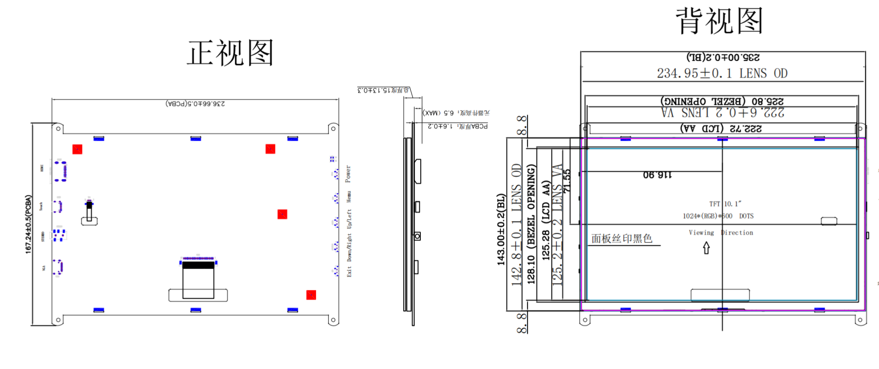
Module outline (HxVxD) | 236.66(H) ×167.24(V) ×15.2(T) | mm |
TOUCH | P+G | |
HDMI interface | 1.4 Receiver | |
Power interface | USB-TYPE-C(+5V) | |
Audio output | 8Ω1WX2 | - |
Temperature Range | 0°C ~ +70°C | - |
Electrical Specifications
Symbol | Values | Unit | Remark | |||
Min. | Typ. | Max. | ||||
Digital supply voltage | VDD | - | 5 | - | V | |
Backlight output voltage | V | - | - | - | V | |
Backlight output current | I | - | - | - | mA | |
TFT output voltage | VDD | - | 3.3 | - | V | |
Interface PIN Connections
Pin.No | Symbol | Function |
1 | HDMI | HDMI-IN |
2 | USB | +5V-IN/USB-TOUCH |
3 | VGA | VGA-IN |
4 | TP | IIC-CAPACITIVE TOOUCH |
5 | TFT-RGB | 50PIN/RGB |
6 | SPK | STEREO 8Ω/1Wx2 |
4.1 TFT-RGB
Pin.No | Symbol | Function |
1,2 | VLED+ | Power for LED backlight (Anode) +9V |
3,4 | VLED- | Power for LED backlight (Cathode) |
5 | GND | Power ground |
6 | VCOM | Common Voltage 3.2V-4.5V |
7 | VDD | Digital Power 3.3V |
8 | VDD | Digital Power 3.3V MODE=DE MODE |
9: | DE | Data Enable signal. |
10 | VSD | Vertical sync input. Negative polarity |
11 | HSD | Horizontal sync input. Negative polarity |
12-19 | B7-R0 | Blue Data |
20-27 | G7-G0 | Green Data |
28-35 | R7-R0 | Red Data |
36 | GND | Ground |
37 | DCLK | Colock signal |
38 | GND | Ground |
39 | SHLR | Left or Right Display Control |
40 | UPDN | Up / Down Display Control |
41 | VGH | Positive Power for TFT +18V |
42 | VGL | Negative Power for TFT -6V |
43 | AVDD | Analog Power +10V |
44 | RSTB | Global reset pin. Active low to enter reset state. 3.3V |
45 | NC | Not connect |
46 | VCOM | Common Voltage 3.2V-4.5V |
47 | NC | Dithering setting |
48 | GND | Not connect |
49-50 | NC | Not connect |
4.3 SPK
Pin.No | Symbol | Function |
1 | R- | right channel negative pole |
2 | R+ | right channel positive pole |
3 | L+ | Left channel positive pole |
4 | L- | Left channel negative pole |
4.4 TOUCH
Pin.No | Symbol | Function |
1 | RST | Touch Reset Signal |
2 | VDD | Touch Power supply +3V3 |
3 | GND | Ground |
4 | INT | Touch Interrupt |
5 | SDA | Touch IIC Data signal |
6 | SCL | Touch IIC Clock signal |
Electro-Optical Characteristics
Parameter | Symbol | Condition | Min. | Typ. | Max. | Unit | Remark | |
Viewing Angle range | Horizontal | Θ3 |
CR > 10 | - | 80 | - | Deg. | |
Θ9 | - | 80 | - | Deg. | ||||
Vertical | Θ12 | - | 80 | - | Deg. | |||
Θ6 | - | 80 | - | Deg. | ||||
Contrast ratio | CR | 800 | ||||||
Luminance | Lv |
Θ = 0° | - | 300 | - | |||
White Chromaticity | Xw | - | 0.307 | - | ||||
Yw | - | 0.338 | - | |||||
Reproduction of color (C light) | Red | Rx | - | - | - | |||
Ry | - | - | - | |||||
Green | Gx | - | - | - | ||||
Gy | - | - | - | |||||
Blue | Bx | - | - | - | ||||
By | - | - | - | |||||
Color Gamut (C light) | 50 | % | ||||||